a) Build an image glowing dotslocated on the main optical axis in three cases:
1) point S located behind the main focus of the collecting lens.
To build an image, it is enough to establish the course of two rays: the 1st beam is directed along the main optical axis - it passes the lens without refraction. The 2nd one is directed arbitrarily at the lens, but parallel to it we draw the secondary axis and find the intersection point of the secondary axis and the focal plane, i.e. side focus. Since all the rays parallel to the secondary axis are collected in the secondary focus, then the beam selected by us will pass through the secondary focus. The intersection of this ray with the 1st ray will give the image of a luminous point S 1 .
 2) point S located between the main focus and the optical center of the lens. The construction is similar to the previous case, but the rays emerging from the lens diverge, we find, continuing the rays to the left, the point from which they supposedly exit, this is the imaginary image of the point S 1 .
3) The luminous point is on the secondary axis.
a) for focal plane collecting lens.
 To build an image, you can use any two of the three rays:
Ray 1 from point S held parallel to the main optical axis, after refraction, it goes through the main focus. Ray 2 carried along the secondary axis, i.e. through the optical center; he passes the lens without refraction. Ray 3 passes through the main focus; after refraction in the lens, it runs parallel to the main optical axis. The point of intersection of these rays after refraction in the lens S 1 and determines the position of the actual point image S ad hoc.
b) Point S located between the focal plane of the collecting lens and the lens itself. We spend three of the same beam as in the first case. Intersection point of any two of them S 1 determines the position of the imaginary point image S.
c) The point is located on the secondary axis of the diffusing lens.
In this case, from the point S the same three cases are carried out, but it should be remembered that the lens is diffusing, then the beam incident on the lens in parallel, after refraction, proceeds as if it is out of focus, which is on the same side of the lens, where the point S. Ray 3 directed to another focus, it hits the lens and then goes parallel to the main optical axis. All three beams supposedly go out of point S 1, which is the imaginary image of a point S. The diffusing lens always creates an imaginary image.
c) Building images of the object created by the lens.
The object is depicted by an arrow perpendicular to the main optical axis. The image of an object is a collection of images of its individual points; therefore, it suffices to find an image of two extreme points (or even one).
Various cases of building images of an item in a collector are shown in the figure:
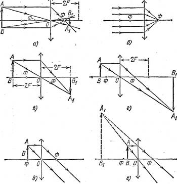
If the item is at a distance:
a) more double focal, the image is obtained real, inverted and reduced.
b) in the limiting case, when the object is infinitely far - the image is in the form of a point, in focus.
c) the subject is in double focus - the image is real, inverted, full-scale.
 d) the subject is at a distance greater than the focal, but smaller double focal - the image is real, inverted, magnified.
e) the subject is in the main focus - the image is obtained infinitely far or in fact it does not exist.
e) the object is between the focus and the lens - the image is imaginary, direct enlarged.
The diffusing lens always gives an imaginary, reduced and direct image of an object that is between the main focus and the lens.
 4. Derivation of the formula of conjugate points of a thin lens.
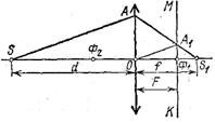
The luminous point and its image in the lens are relocatable, i.e. if the luminous point is placed where its image was, then the image is obtained where the luminous point was. therefore S and S 1 conjugated. Consider two pairs of similar triangles:
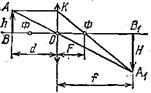
Denote, then we have:; in proportion property: ( d+ f) (f– F) = f 2 ; df + f 2 – dF – fF = f 2 ; df= dF+ fF; divide by dfFget or
- the formula of conjugate points of a thin lens.
d and f can be swapped.
 5. Linear magnification obtained with a lens.
Linear increase b call the ratio of the height (width) of the image of the object to the true height (width) of the object itself:. H - image height; h- the height of the subject. ![]()
Obviously, a collecting lens gives an increase only in cases where the image is farther from the lens than the object.
Optical instruments.
a) The projection device is designed to receive on the screen an enlarged image of drawings, drawings, etc .: if the image is projected from a transparent object, then the device is called diascopeif not transparent - by bishop. The combined unit is called an epidisk. Fig. 31.1.
The lens that creates an image of an object in front of it is called lens. Two flat-convex lenses form a condenser that collects light rays from the source on the lens ABOUTand the lens directs the rays to the screen where the image of the slide is obtained D. Slides placed between the main at a distance from the lens of a large focal, but smaller dual focal. The sharpness of the image on the screen is achieved by moving the lens.
b) Camera - is an optical device designed to take photographs of objects in front of him. It consists of an opaque camera with a movable front wall in which the lens is located. 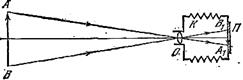 Focusing is done by moving the lens; the lens opens at a certain time called shutter speed. On the film, a latent image is obtained and after manifestation it is negative; perevechivaya negative on photo paper, get a positive (photo).
at) Magnifier - one of the simplest optical devices. This is a collecting lens designed for viewing enlarged images of small objects. Increase optical instrument call a number indicating how many times the angle at which the eye sees an image of an object in the device is greater than the angle of view, at which the eye sees an object without an instrument:
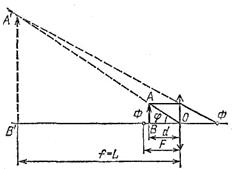 because corners j and j 0 small.
The subject viewed in a magnifying glass is placed in the focal plane of the lens or not much closer to the lens and is visible at an angle jwhich is more angle j 0 - under which the eye sees an object from the best possible distance j 0 and magnifying loupe:
![]() ; because L = 0.025m, then
; because L = 0.025m, then
- increase the magnifying glass.
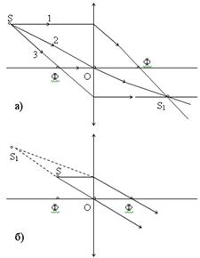
With the help of the lens you can collect in one point not only parallel rays. Experience shows that the rays falling on a collecting lens from one point S, after the lens are collected again at one point S1 (Fig. 30.8, a), i.e. the lens creates a real image luminous point S at point S1. This image may be imaginary. In fig. 30.8, b shows the course of the rays falling from point S on the scattering lens. After the lens, they go in a diverging beam, but so that their extensions in the opposite direction converge in S1. Let us find out how the image of a luminous point created by the lens, located on the main optical axis of the lens, is constructed in three cases.
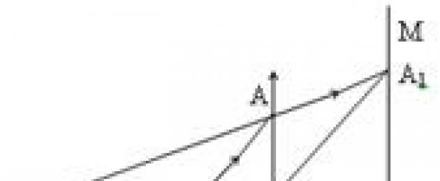
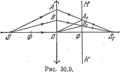
1. Point S is located behind the main focus of the lens F (fig. 30.9). Since at the point S1 all the rays converge after refraction in the lens, then to determine the position points S1 is sufficient to establish where two such rays intersect.
Let direct DF is the main optical axis of the collecting lens, and KM is the focal plane of this lens. The beam coming from the S point along the main optical axis passes the lens without refraction, therefore the image of the S point will be located on the main optical axis of the DF. In order to find out exactly where the image of point S will be, let's find the course of an arbitrary beam SA after the lens. To do this, from point O we will conduct a secondary optical axis parallel to the beam SA. It will cross the focal plane of the CM at some point A1. A straight line drawn through points A and A1 sets the course of the beam SA after refraction in the lens. Continuing the straight line AA1 to the intersection with the main optical axis, we obtain the point S1, which determines the position of the image of the point S, created by the lens. It is clear that any other SB beam, after refraction in the lens, will also pass through point S1 (Fig. 30.9); the secondary optical axis OB1 is parallel to the SB beam.
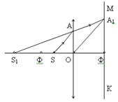
2. Point S is located between the main focus and the optical center of the lens (Fig. 30.10). As in the first case, the image of point S will be somewhere on the main optical axis. To establish exactly where, select an arbitrary ray.SA, falling on the lens. We will conduct the secondary optical axis OA1 parallel to SA, and then the straight line AA1 to the intersection with the main optical axis at point S1. The latter determines the position of the imaginary image of point S for the case under consideration.
![]()
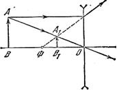
3. The luminous point is located on the main optical axis of the diffusing lens (Fig. 30.11). When building an image in this case, the focal plane must be taken from the same side of the lens as the point of the Image of the luminous point S and in this case must be on the main optical axis of the lens. Select an arbitrary raySA and conduct parallel to him the secondary axis OA1. The point of intersection of the straight line AA1 with the main optical axis will determine the position of the imaginary image S1. Note that the image of a real point source of light in a diffusing lens always produces an imaginary one.
When the luminous point is on the side optical axis of the lens, the lens creates its image on the same axis. Let's find out how this image is built.
1. The point is located behind the focal plane of the collecting lens (Fig. 30.14).
To determine the position of the image, you can use any two of the three rays shown in Fig. 30.14. Beam 1 of the point is held parallel to the main optical axis. After refraction in the lens, it goes through the main focus. Beam 2 is conducted along the secondary axis, i.e., through the optical center of the lens. This beam passes the lens without refraction. Beam 3 is conducted through the main focus F. After refraction in the lens, it goes parallel to the main optical axis. The point of intersection of these rays after refraction in the lens determines the position of the real image of the point for this case.
2. The point is located between the focal plane of the collecting lens and the lens itself (fig. 30.15). In this case, from the point you can spend three of the same beam as in the first case. The point of intersection of any two of these are determined by the position of the imaginary point image
3. The point is located on the secondary axis of the diffusing lens (Fig. 30.16). And in this case, three of the same rays can be drawn from the point (as in the first case), but remember that after refraction in the lens, the continuation of ray 1 must pass through the focus that is located on the side of the lens where ray 3 must be so that its continuation passes through the focus of the other side of the lens, then after refraction in the lens, the beam will go parallel to the main optical axis. Notice
- In contact with 0
- Google+ 0
- OK 0
- Facebook 0